Neighborhood Cabinets

In this design, you have a series of above ground cabinets (I called them cabinets because they are bigger than a typical pedestal). For 6,000 customer locations, you might have 20 cabinets, or about 300 customers per cabinet. You would run backbone cable to each cabinet and terminate your 288 or 576 count cable onto connectors. You then could have ducts or direct burial fiber cable going to each property. For suburban lots, you might have one duct per house, or share a duct for a pair of houses. The cabinet is basically a big cross connect with integrated splice trays (no need for splice closures since the cabinet acts as a splice closure as well). In addition, it would also house PON splitters if you are using a PON architecture.
It is easy with this architecture to offer many types of services for the area served by the cabinet. You can offer 1-32 split GPON, or point to point, or a dedicated fiber for a cellular backhaul, or fiber to a utility. You can either initially overprovision the cabinet with backbone fiber, or just have extra conduit space to pull a new cable when customer demand exceeds the pulled number of fibers.
Here's an example of a suburban neighborhood served by a single cabinet.

Conduits, Microducts & Direct Bury
When you lay fiber in the ground, you have at least three different ways of doing this.
You can lay conduits that are large enough to accomodate more than one fiber cable. A 1 1/4" conduit like this one:

Can be filled with more than one cable, and in theory at different times. ie. you can pull or blow a backbone cable through this conduit at initial construction and years later, you could add another cable in the same conduit.
More commonly these days, people are opting to use microducts:
 Image source: Duraline
These are smaller diameter ducts than are just big enough for the appropriately sized cable to be blown through. Backbone sized microducts can be installed as a bundle to allow spare empty backbone ducts, allowing you to have extra empty ducts for future expansion rather than laying fiber for future expansion. And ducts that serve one or two houses can be very small for the much smaller cable that is required.
During construction, microducts can be joined through handholds to allow for a very long continuous duct which allows for far reaching fiber cable to be blown for quite a distance in one go.
Finally, you can opt to not use conduit or ducting at all and just direct bury the cable with armored cable. This is quicker, easier, and less costly. The downside is that you have to retrench should you want to expand your backbone network and pull additional fibers.
Distributed Splice Closures
If your customers are more spread out, yet still somewhat clustered, you can use splice closures for all your customer drops. Here's a layout from the Michaelston-y-Fedw network showing how they have many spread out pockets of customers (red circles and stars are customers).

Image source: Michaelston-y-Fedw Internet CIC
In this architecture, a backbone cable comes into and maybe leaves the splice closure, while a number of buffer tubes are split off and spliced onto customer drop cables. In this image to the right, this splice closure serves many customer microducts.
Due to Michaelston-y-Fedw's unique government subsidy arrangement, they do not expect to need to serve too many customers that didn't initially sign up for the initial build out. This means they don't expect to have to go back to their splice closure and open them up very often. It gives them the ability to just use fusion splicing for the build out, and not use any connectors in the field.
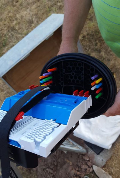
Terminals
A terminal is a fiber end point that ends with connectors. Instead of using fusion splicing to extend the fiber network to a house drop, you use a drop cable that has a field connector on one end that plugs into the terminal. This makes it easier to add new houses after the initial backbone network is constructed - no fusion splicing is needed.
Shown here is an example of such a terminal.

All terminals must have some way of protecting their connectors from water intrusion. In this case, these are special "Optitap" connectors (an open source industry standard) that can screw onto the terminal's external connectors forming a water tight connection.
All terminals will have a "tail" which is multi fiber cable that will run back through conduit to the nearest splice closure for fusion splicing to the backbone cable.
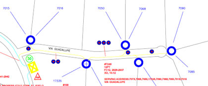
You might use such an 8 port or 12 port terminal in a design like this one where a terminal is in an underground vault and serves several distributed houses (the circle with the X is where such a terminal would go to serve the other locations via buried flower pots):
You can also extend your terminals all the way to the property edge if you use many 2 port terminals like this one shown here:

In this design, you would leave such a 2-port terminal in a small "flower pot" at grade level to serve two houses.
If you use terminals, you must make sure that the connections are waterproofed, just as you do for splices.