Overview
If you're looking to do a really small network for maybe 20 or so houses, see this much simplified design.
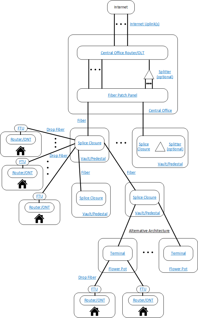
This diagram shows all the major components of a FTTH network. Each blue underlined phrase is a link to the appropriate description page for that element.

It starts at the top with fiber(s) connecting an Internet uplink to the central office router. The router then has many ports either connecting to a patch panel or directly to FTTH network fibers leading to customers. Optionally, you can have optical splitters if you are using a central office GPON splitter architecture.
Backbone fibers are routed through the neighborhood and pass through below ground vaults or above ground pedestals and into splice closures. Inside the waterproof splice closures, some backbone fibers are peeled off the backbone cable and spliced onto drop fibers going to houses, and/or spliced onto lower fiber count backbone cables going deeper into the network.
At the side of the house, a Fiber Termination Unit (FTU) is placed that terminates the drop fiber onto a connector. A flexible fiber cable is then run through the house to the fiber router or Optical Network Terminal (ONT) which then provides 1 Gbps Ethernet, WiFi and possibly other services such as telephone or TV.
If you are using a field splitter GPON architecture, you would have optical splitters either in the splice closures or beside the splice closures in the vaults/pedestals.
An alternative architecture is to splice a separate terminal near each customer in a smaller underground vault, such as a "flower pot" so that when a customer is ready for a connection, a cable need only be run to the terminal rather than further back to a splice point.